General Precautions
Cylinder head
Fuel oil pipe
Fuel Nozzle
Exhaust valve
Intake valve
Valve clearance
Starting
air valve
Piston overhaul
Connecting rod
Crankpin
bearing
Cylinder liner
Sole plate
Main bearing
Thrust bearing
Crank shaft
Timing gear
Cam shaft & Cam
Adjustment
of cam
Fuel Injection system
Governor
Intercooler
Fuel
oil system
L.O.system
Cooling
water system


|
General
Precaution
General Precautions for Disassembly, Assembly
and Adjustment Prior to disassembly, assembly and/or adjustment
of engine, the engine internal construction and standard adjustment
procedures should be fully understood, and the standard maintenance
procedures to be described herein read thoroughly.
1. Handle
the engine and other parts carefully. ¡°safety
first¡± should always be your slogan.
2. Give heed to the assembly sequence and tally marks to avoid mis-assembly.
3. When disassembling jointed parts, pay special attention to the
match marks. If the match marks are not provides or are blurred,
mark them clearly. When overhauling parts associated with specific
cylinder numbers mark them with paint or magic pen so that can be
clearly identified in assembly.
4. Each disassembled part should
be put in a designated box or the like container in good order or
kept nearly in designated places to avoid misplacement.
5. Do
not mix the special heat-resistant bolts and nuts used with the
exhaust pipe, etc. (exposed to high temperature) with other kinds
of bolts and nuts in assembly.
6. Tighten bolts and nuts with
force observing the correct tightening torques, as specified each
engines.
7. Check periodically for looseness of bolts and nuts
for internal components which are not overhauled.
8. If turning
is necessary midways in disassembly or assembly, ensure that there
are no parts that may come into contact with the rotary part and
that there is no danger to the personnel working nearly.
9.
Use standard tools when disassembling and assembling the engine.
10. When disassembling, take specified measurements at as many points
as possible; data thus gained should be filed for later reference.
11. Packings should be replaced at each disassembly. So a sufficient
number of packings should be a hand to match the degree of disassembly.
12. When some spare parts are used, replenish them at once.
13. From the viewpoint of full utilization of engine performance,
with appropriate periodic overhauling intervals, and of the interchange
ability and accuracy of the parts used.
14. Cover each of disassembled
parts without fail to keep out dust.
15. Before assembling,
make sure that all parts are clean. If any are soiled, wash with
gas oil, or airblow clean.
Cylinder Head
Overhauling process
1. Remove cylinder head top cover.
2. Disconnect
all piping around cylinder head.
3. Remove rocker arm shaft
holder.
4. Disconnect high pressure fuel pipe.
5. Remove
cylinder head lower cover
6. Remove push rod and protective
sheath.
7. Remove cooling water regulating cock.
8. Remove
nozzle holder
9. Unscrew exhaust pipe fixing bolts.
10.
Unscrew intake air pipe fixing bolts.
11. Remove indicator valve
12. Remove cylinder head tightening nuts.
13. Remove cylinder
head.
<Precautions>
1. When detaching cylinder head, take care not to Damage
fit-up surface of o-ring fitted to cooling water guide.
2. Before
scraping carbon deposits from combustion chamber, check deposit
condition and quality.
3. Remove carbon deposits from combustion
chamber and carefully check for cracks.
4. Since cylinder head
packing has the important function of sealing high pressure gas,
always replace it, insofar as possible , at each overhaul.
Since
cylinder head packing seat section is susceptible to flaws give
special care to handling.
5. Check for corrosion on fit-up surface
of o-ring for cooling water guide, and also for gas leakage through
cylinder head packing. Minor corrosion or gas leakage should
be corrected at once.
6. Check and remove fur accumulated on
water jacket of cylinder head at least once every two years. If
not cleaned for a long time, cooling efficiency drops, water passage
is clogged and cracks may develop.
7. Upper surface of cylinder
head serves as return passage for rocker arm lubricating oil. Clean
this surface with care so that foreign matter such as dust or cotton
waste, etc. does not enter lubricating oil.
8. When lifting
cylinder head, life it horizontally. Take care not to allow water
inside jacket to enter cylinder.
9. Loosen cylinder head fixing
nuts gradually the sequence shown below, so that all are loosened
completely after second run. Loosening each one fully at once will
exert undue strain on other bolts still tightened firmly. Proceed
in the same manner also when tightening to fix cylinder head.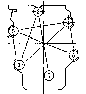
10. When
loosening cylinder head tightening nuts, use a box spanner. Use
torque wrench only for tightening.
Take special care in setting
cylinder head so as not to scratch or dent packing surface of cylinder
head or liner or fixing nut. Clean thoroughly to remove dust, etc.
before fixing.
Tighten intake/exhaust pipe fixing bolts prior
to tightening cylinder head fixing nuts. Cylinder head adjust intake/exhaust
pipe flange face to face.
High
pressure fuel oil pipe
When connecting high pressure fuel oil pipe to nozzle
holder or disconnecting it, use double spanners so no torque
will be exerted on inlet connector.
High pressure fuel oil pipe
should be handled with good care as it is subject to very high pressure.
Special care should be taken not to scratch the fit-up surface
of each fitting and joint.
<Disassembly
procedure>
1. Remove o-ring guide set
bolts
2. Displace o-ring guide toward holder side.
3. Using
special spanner provided, remove cap nut at holder side.
4.
Displace tube retainer upward.
5. Loosen cap nut at pump side.
6. Rotate nozzle holder sideways and detach fitting to high pressure
pipe from nozzle holder.
7. Extract nozzle holder.
Fuel nozzle
Since
maintenance of the nozzle has a great effect on the condition of
combustion and output, be sure to disassemble and inspect it whenever
any change in exhaust gas temperature or color is noted.
Be
sure to use the nozzle specified on the factory operation data sheets.
Before removing nozzle, check condition and quality of carbon deposits.
<Nozzle injection testing> 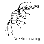
1. Detach the high pressure fuel oil
injection pipe and other piping , and remove nozzle from cylinder
head using nozzle holder disassembly tool.
2. Before removing
nozzle, measure and record nozzle injection pressure.
3. Remove
pressure adjustment bolt cover of nozzle holder, loosen pressure
adjustment bolt.
4. After removing carbon deposits, detach nozzle
from holder.
5. Clean carbon from nozzle tip.
6. Attach
nozzl eot nozzle testeras specified on assembly.
<Precautions>
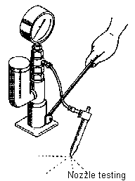 1. Operate the nozzle tester hand lever at as stroke
of 4¡6 time per second and check the spray mist to see that it
is uniform without abnormality due to the blocked injection hole.
Shown below are different condition of fuel spraying through
injection nozzle. 1. Operate the nozzle tester hand lever at as stroke
of 4¡6 time per second and check the spray mist to see that it
is uniform without abnormality due to the blocked injection hole.
Shown below are different condition of fuel spraying through
injection nozzle.
2. When removing nozzle, be sure to loosen
nozzle holder pressure adjustment bolt. When remounting, pressure
adjustment bolt should be loose. Nozzle removal/remounting with
pressure adjustment bolt tightened may damage needle and cause mal-injection.
3. In nozzle testing, check carefully also for wear or corrosion
of needle valve, and replace it if worn. Special care should
be taken as to injection port wear, which is likely to occur when
heavy fuel oil is used.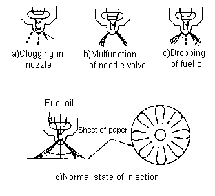
4. Check for smooth movement
of nozzle and needle; replace if either is stuck.
5. Do
not fit nozzle and needle with lapping agent.
6. Nozzle
and needle are used as a pair; do
not intermix pairs.
After cleaning nozzle
and needle of carbon, wash in clean gas oil and air-dry.
7.
Before fitting tested nozzle to nozzle holder, clean mating faces
thoroughly to remove dust or other foreign matter; then tighten
with correct torque as specified in the Tightening Torque Table
shown in each engine instruction book. Tightening with excessive
torque may result in sticking of needle valve.
8. Since the
high pressure fuel injection pipe is subject to very high pressure
during operation, install it without imposing any stress. Check
occasionally for loosening of joints of high pressure fuel injection
pipe and other piping as it may cause leakage of oil into rocker
arm lubricating oil.
Exhaust valve
1. Exhaust valve seat is pressure-fitted into cylinder
head. Therefore, exhaust valve should be fit with cylinder head
overhauled.
2. Exhaust valve fitting is the most complicated
maintenance task. Although the interval of maintenance varies
depending upon load ratio, combustion condition, fuel oil grade,
etc., it is advisable to conduct the first round maintenance as
early as possible and then to prolong the interval according to
the circumstances.
3. Measure clearance between valve stem and
valve guide at the time of inspection of extracted valve. Excessive
clearance may result in gas leakage or breakage of valve spring.
Replace valve stem or valve guide, whichever is worn more.
4. For fitting valve, first coat with proper amount of fitting agent
and fit using intake and exhaust valve fitting tool. Use ¡°Medium¡±
to ¡°Fine¡± fitting agent. Then, wash the valve well and perform
final fitting with machine oil. Since exhaust valve and valve seat
are very hard because of stellite reinforcement, it is desirous
to use grinding for dressing the fit-up face. Valve should
be fit with bet care, sparing enough time for obtaining good fit.
5. If valve seat is worn excessively, dress the seat face by either
machining or with grinding tool. Grinding tool is optionally
available.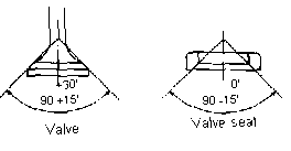
When repairing either exhaust valve
or exhaust valve seat, finish the seat portion to the angle as shown
below, so that the valve will be seated harder at the combustion
chamber side.
6. Frequent fitting of valve or frequent machining
tends to widen the seat width. When the valve has worn beyond the
allowable wear limit, replace it with newone.
7. Machining of back side of valve is prohibited as it lowers the valve strength.
<Disassembly
procedure>
1. Set intake/exhaust valve
extraction tool to the nozzle holder guide hole on top of cylinder
head.
2. Holding the spring by turning the bolt, extract cotters.
<Precautions>
1. Valve spring cotters are manufactured as a
pair. In disassembly and assembly, be sure to keep them together
and use them on the same valve.
2. Check valve spring for cracks
with color penetrant.
3. Check valve rotator.
4. When assembling,
do not forget to insert valve retaining ring into groove on valve
stem.
<Check items>
1. High temperature corrosion of valve head.
2. Sulfuric acid corrosion or bend at valve stem.
3. Blow-by
or pitting at valve seat
4. Fit-up at valve seat
5. Fit-up
at valve stem end
6. Valve spring caking or corrosion (check
via color penetrant test as necessary)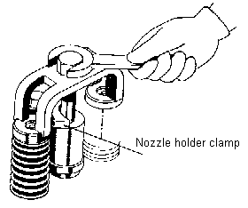
Intake valve
1. Intake
valve seat is pressure-fit into cylinder head. This part should
be fitted when overhauling cylinder head.
2. When clearance
between valve stem exceeds the allowable wear limit, replace stem
or guide, whichever is worn more.
3. When valve seat exceeds
specified repair limit after machining or due to wear, replace it
with new one.
4. Fitting of intake valve and valve seat.
a) Intake valve and valve seat should be fitted carefully, as with
exhaust valve. Wash it well and perform final fitting with machine
oil.
b) Heavy scratching or dents on face or seat portion of
intake valve should be rough dressed by machining or with valve
seat cutting tool. Do not forget to fit after dressing.
When repairing either intake valve or intake valve seat,
finish the seat portion to the angle as shown each engine instruction
guide, so that the valve will be seated harder at the combustion
chamber side.
Adjustment
of valve clearance
If clearance at valve end is too
small, valve stem and push rod will by heat during operation causing
improper valve seating, which may result in
damage to valve or improper combustion.
Conversely, too large a clearance may cause an increased
level of noise in operation or damage or abnormal wear in the valve
operating mechanism.
Therefore, maintaining
the right amount of clearance is essential for normal operation.
Valve operating mechanism in the engine presses two intake valves
(or exhaust valves/or one and one) simultaneously with one T-shaped
yoke.
If the heights of these two valves fail to agree precisely,
imbalance in the valve pushing force will cause valve or valve holder
to fall, leading to abnormal valve guide wear or valve damage. To
avoid this, adjust valve end clearance in the following procedure
after valve maintenance.
(Follow up each engine maker's instruction)
<Measurement
of valve end clearance>
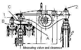 1. Bring intake
and exhaust valves for cylinder to be measured to fully closed positions.
(At this position, graduation marked on flywheel points to TOP position
, with the marked line on the fuel injection pump at the up position.) 1. Bring intake
and exhaust valves for cylinder to be measured to fully closed positions.
(At this position, graduation marked on flywheel points to TOP position
, with the marked line on the fuel injection pump at the up position.)
2. Loosen lock nuts and unscrew clearance adjusting screw 1 and
2.
3. With valves contacting firm at end A, adjust with screw
1 so that the other end fits closely at B.
4. With adjusting
screw 1 held securely via spanner applied to the square head, tighten
lock nut firmly.
5. Insert a feeler gauge of the specified thickness
at part C and adjust screw 2 in the same manner as for screw 1.
Starting air
valve
If the starting air valve fitting is improper or
the valve rod or the starting air valve piston becomes struck, gas
counter flows into the main starting air pipe, causing sticking
of the starting rotary valve and starting air valve and thereby
damaging them. For this reason , it is necessary to perform the
fitting work with care.
Operational overheating of starting
air pipe is caused by gas leakage from starting air valve. Check
valve at once and stop leakage.
It is recommended that starting
air valve fitting be done together with the intake valve.
<Disassembly>
1. Remove starting air valve piston case.
2. Remove split pin for tightening nut of starting air valve spring
seat and remove nut.
3. Remove starting air valve spring seat
and spring.
4. Pull out starting air valve rod to combustion
chamber side.
<Precautions>
1. Do not tighten tightening nut of starting
air valve seat with excessive force, otherwise, screw parts
of valve rod may be broken and valve rod drop during operation.
2. Divide split pin carefully, making sure that it does not touch
starting air valve piston.
Piston overhaul
Piston overhaul intervals differ according to
the degree of daily maintenance, especially to the control of lubricating
oil. Since appropriate overhauling interval varies with the
individual engines, it is to be decided by the judgement of the
person in charge of the engine.
It is recommended that an optimum
schedule be arranged by match the individual conditions using the
maintenance intervals shown on each engine instruction of makers.
Interval can also be judge by the amount of lubricating oil consumption.
As lubricating oil deteriorates its consumption increase due to
sticking in rings and increased blow-by.
If consumption is double
the normal level, overhaul must be considered, with replacement
of rings as necessary.
<Piston
extraction procedure>
1. Remove carbon
accumulated in the combustion chamber at the upper part of cylinder
liner.
2. Remove set bolt for connecting rod lock washer and
take out washer.
3. Set crank pin at 20¢ª¡30¢ª past top dead
center in the crank normal rotation direction and pull out connecting
rod bolt.
4. Remove connecting rod cap.
5. Attach piston
lifting ring to top of piston and lift it up.
6. Place piston
at designated place. After removing piston pin retaining ring, extract
piston pin while holding the connecting rod.
<Piston assembly procedure>
1. Set piston pin and connecting rod.
2. Insert piston pin retaining
ring in the groove.
3. Fit piston insertion frame to the upper
part of liner.
4. Attach piston lifting ring to top of piston
and lift it up.
5. Set crank pin at the same position as for
disassembly, and insert piston slowly into the liner using the piston
insertion frame as a guide.
6. Fit connecting rod cap from beneath;
tighten connecting rod bolt to specified torque and fit lock washer.
<Precautions>
1. When loosening connecting rod bolt, use a spanner. Do not
use a torque wrench for this purpose.
2. Be sure to use a torque
wrench when tightening connecting rod bolt and tighten correctly
referring to Tightening Torque Table shown on each engine instructions.
2. Since carbon is likely to deposit in hole for piston lifting
ring, be sure that the ring is screwed in firmly. It may be
advisable to clear threads with a tapping tool beforehand.
3.
When extracting and replacing piston , take care not to damage crank
pin bearing and serrated section of connecting rod.
4. Be careful
not to damage crank inner surface of liner with the large end of
connecting rod.
5. Before inserting piston in the liner , lubricate
all the sliding parts ( outer surface of piston, liner and bearing)
with lubricating oil. Except for the back face of bearing.
6.
Be sure to align match marks of connecting rod and cap when assembling.
7. When extracting piston , be careful not to allow connecting rod
to contact piston cooling system.
8. Take care not to damage
crank pin with serrated portion of connecting rod.
9. When positioning
piston, be sure not to confuse
intake (I) and exhaust valve sides (E).
10. With incorrect positioning, intake valve will strike upper part
of piston, potentially leading to a serious accident.
11. When
inserting piston into liner, tap periphery lightly piston with a
plastic hammer or the like. If it cannot be inserted smoothly, do
not force it; lift piston temporarily and re-insert.
12. Thoroughly
remove carbon deposits from piston and liner.
Piston
1.
When extracting piston, carefully check carbon deposit and condition
of lubricating oil drip and record the findings for reference for
use during later maintenance.
2. Check for any abnormal contact
marks on the piston or seizing in rings.
3. Check the condition
of scale deposit inside the piston from back side.
4. Check
at piston cooling oil inlet for contract marks caused by interference
with nozzle.
5. Check for any abnormal contact marks on piston
pin and pin boss parts.
6. Scale off carbon deposit on the piston
thoroughly. After washing, measure dimensions of all the parts.
Use fine grain sand to scale off carbon deposit, except for
the piston skirt part; avoid use of sand paper here, which would
damage special coating. (When FCD piston is used)
Piston ring
1. If Piston ring is consisting with chrome plated, check the plated
layer is abraded or not, the abraded ring should be replaced with
a new one.
2. At the time of periodic overhaul of piston , replace
the rings in consideration of the length of operating time until
the next overhaul.
3. Measure each part after removing carbon
and oil completely.
4. Since oil ring quality affects lubricating
oil consumption, special care should be taken in this regards.
a) After a long period of operation, circumference of each ring
will have become sharp edged. Therefore. Be careful in handling
them and wear gloves during overhaul.
b) When mounting ring,
place the marked side up (toward the combustion chamber), and set
in the correct order.
Connecting rod
1. Check serrated mating surface at large end
of connecting rod for cracks or wear.
2. Check if piston pin
bearing at small end fits firmly in position with proper fit-up.
3. Measure bore of bearing and outside diameter of piston pin and
check that dimensions are within allowable wear limit specified
each engine instruction. When replacing piston pin bearing
worn beyond the allowable wear limit, remove it with a press or
by driving it out, confirm position of the oil hole on new bearing
and press it in.
4. When too large a load is applied to the
engine as a results of piston seizure or water hammer, connecting
rod may have bent or fallen. Accordingly, at overhaul, connecting
rod should be thoroughly examined for cracks by color check. However,
such checking is not required at periodic overhaul.
Crank pin bearing
1. When detaching crank pin bearing from connecting
rod, lightly tap notch side of back shell with a piece of wood to
create a gap between shell and bearing housing for easier removal.
2. Check condition of crank pin bearing with care and measure how
much it has abraded.
3. To ensure that crank pin bearing maintains
close contact with surface of housing, crank pin bearing shell
must have proper crush and tension. Refrain from using files or
scrapers at any time.
4. If crank pin bearing must be replaced,
replace upper and lower shells
at same time.
5. On assembling crank pin
bearing, thoroughly wipe dust or other foreign matter from housing
and shell back face. Refrain from applying any grease or lubricating
oil to back face of shell. Align notches so that direction of bearing
will not by mistaken. Tap center part of bearing by hand a few times
to fit it with housing.
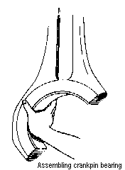 6. Even if bearing abrasion
is still within the allowable limit, if it is used for a long time,
it loses tension. Which may cause cracks. Therefore, it is better
to replace it with a new one after 4 years or so of operation. 6. Even if bearing abrasion
is still within the allowable limit, if it is used for a long time,
it loses tension. Which may cause cracks. Therefore, it is better
to replace it with a new one after 4 years or so of operation.
7. If bearing check is required while engine is stopped, disassemble
and check bearing by lifting piston via piston supporting tool.
a) Bring piston in cylinder to top dead center.
b) Detach nozzle
holder from cylinder head.
c) Insert piston supporting ring
into hole on nozzle holder and screw it into threaded hole provided
at the upper rod bolt, remove cap at large end and disassemble bearing
for inspection.
d) Loosening connecting rod bolt, remove cap
at large end and disassemble bearing for inspection.
Tightening of connecting rod bolt
Be sure to tighten
connecting rod bolts firmly.
Poor tightening may result in damage
to bearing metal or serrated portion at large end, or to a catastrophic
accident such as bolt breakage.
1. Handle
parts carefully so as not cause scratches, dent or deposition of
dirt on screw portion of bolts and connecting rod contract surface.
2. Roughening or scratching on bolt threads or seat surface may
result in poor tightening ;to ensure firm tightening , spray anti-seizure
agent (MOLYKOTE 1000 spray type) Over these surfaces.
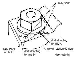 Roughness or
scratches on surface, if any, should be repaired by machining or
otherwise. Roughness or
scratches on surface, if any, should be repaired by machining or
otherwise.
3. Screw the bolt into the original hole from which
it was removed.
4. At first screw bolts by hand and check without
any resistance.
5. Tighten
bolts as following procedure
a) First
confirm the match marks punched at (A) and (B) on large-end cap
shown below.
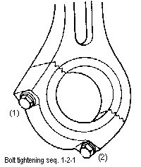 b) Attach large-end cap without bearing
metal; using a torque wrench, tighten bolts to torque A (follow
as specified each engine) b) Attach large-end cap without bearing
metal; using a torque wrench, tighten bolts to torque A (follow
as specified each engine)
Tightening
sequence;
Bolt ¨ç- Bolt ¨è- Bolt ¨ç
c) Punch tally mark on bolt heads to match with (A) marks on large-end
cap.
d) Attach bearing metal and install in engine. Tighten
bolts with torque wrench of the specified capacity. Be sure to tighten
them by two steps.
Tightening sequence;
1 st step : At torque
A
Bolt ¨ç- Bolt ¨è- Bolt ¨ç
2 nd step : At mark B
Bolt
¨ç- Bolt ¨è- Bolt ¨ç
Note)
1. Anti-seizure (MOLYKOTE 1000
Spray type) should be used to bolt seats and threads before tightening.
2. At connecting rod bolts, A torque and rotation angle should be
the first concern, B torque is for reference only.
e) After
tightening to mark B, check tally marks on bolts coming to B position
on lock washer in place.
After
long term operation, each parts become running-in condition, resulting
in some deflection of the relative positions of bolt and large end
cap.
Therefore, bolt tally marks cannot be reused after extended
operation; punch new marks. When tightening bolts to new marks,
distinguish new marks from conventional marks.
6. After installation, check
side motion of connecting rod without fail to secure the appropriate
clearance between rod metal and shaft. After test running, thoroughly
check, by hand touching, that there is no abnormality; and then
start normal operation.
Cylinder liner
1. Wear of cylinder liner bore differs according
to fuel oil grade, control condition of lubricating oil and temperature
of cooling water , etc. As progress of wear leads to such
problems as blow-by, increased lubricating oil consumption, etc.,
cylinder liner worn beyond the allowable limit as specified each
engine, should be replaced with a new one at an early stage. Because
of initial wear , a newly built engine generally shows slightly
more wear in its cylinder liner at this time than at other stages.
2. Remove carbon deposited on cylinder liner when overhauling and
inspect and measure each part with care.
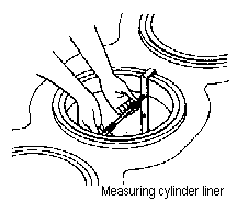 <Measurement> <Measurement>
Set liner wear locating deposited in the axial direction and
the normal rotation direction. Measure wear by cylinder bore
gauge.
3. If air is mixed in cooling water, cavitation may occur
in the liner jacket, and the liner may be corroded from its exterior.
Therefore, desecrate fully, take out liner at least once every four
years to remove fur collected in jacket, and carefully check extent
of corrosion.
<Check
items>
1. Scratches, corrosion, scuffing,
or cracks on sliding surface.
2. Removal of carbon deposits
from upper inner side of liner (Check of jacket side of liner)
3. Cracks on flange fillet (Use color penetrant test)
4. Traces
of erosion by cavitation. Minor erosion may be touched up with ¡°
Devcon¡± etc.
5. Corrosion or fretting at upper and lower parts
of liner, where it is fit to engine frame.
6. Removal of deposits
on jacket side of liner, excepting thin film of rust-preventive
agent (greyish-brown)
7. Cracking where liner is fit to engine
frame (color penetrant test). Peeled rust preventive coating on
water jacket in engine frame should be repainted.
< Extraction and insertion>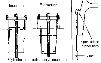
1. Cylinder liner is extracted and inserted using cylinder liner
extraction tool as follows.
2. Align marks on liner and engine
frame when inserting new liner.
3. When reassembling, replace
upper packing, liner rubber ring and o-ring.
4. Since liner
rubber ring and o-ring are watertight to seal between lower part
of jacket and crankcase, take special care in fitting so as not
to break them. Apply silicone rubber to prevent possible corrosion
at the clearance. However, do not apply silicone rubber to
o-ring.
Piston cooling unit
1. Piston cooling
nozzle is mounted at the lower part of engine frame. This part should
not be disassembled unless absolutely necessary.
2. Piston cooling
support is assembled with two knock pins. After overhauling
piston , bring the piston to bottom dead center as illustrated below
and check for correct alignment with counterpart on piston using
nozzle locating jig.
Sole
Plate, Crankshaft and Related Parts
Sole Plate
1. When inspecting main
bearing, check for proper fit at spigot-joint part and mating surface,
and for scratches or cracks on these surface, including check of
main bearing cap.
2. Check for loose main bearing bolts, and
re-torque if any bolt has become loose in operation.
3. If excessive
load was applied to main bearing or if crankshaft is burnt measure
dimension of hole on main bearing. Check also for cracks or other
damage on sole plate around main bearing.
4. When main bearing
cap is disassembled for inspection of metal and reassembled, be
sure to set it in proper direction.
Main bearing
metal
1) Since main bearing metal is thin-shell type
as crank pin bearing, no shim should be inserted between sole plate
and bearing metal and no file or scraper should be used.
2)
Since larger clearance may result in cracking, seizure or lubricating
oil pressure drop, periodic overhaul is required. Otherwise, bearing
metal wear causes increased crank deflection, bringing about a dangerous
crankshaft condition due to the application of repetitious stress
by internal moment.
3) Carefully check back side of bearing
metal and mating surface for fretting, traces of seizure of buildup
of foreign matter; measure degree of wear.
<Bearing metal clearance measurement>
1. Metal thickness measurement
Extract bearing
metal and measure thickness.
2. Measurement by means of lead
wire
Extract main bearing cap and put a soft lead wire (0.5mm)
on upper part of crankshaft.
 Then
replace cap and tighten to prescribed torque. Remove cap and measure
with a micrometer the thickness of the lead wire thus pressed. Then
replace cap and tighten to prescribed torque. Remove cap and measure
with a micrometer the thickness of the lead wire thus pressed.
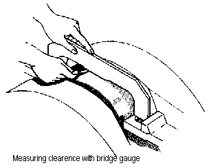
3. Measurement with bridge gauge
Apply bridge gauge across crank
journal and measure clearance between gauge and circumference of
journal. An optional bridge gauge is available.
4. Measurement
of outside diameter of crankshaft and inside diameter of metal
Remove crankshaft from sole plate and measure outside and inside
diameters. This is the most reliable method for obtaining correct
values.
4) When the main bearing metal is worn, replace it with
a new one. When crank journal or crank pin is worn, replace with
an undersized metal. (In this case, crankshaft must be ground accordingly.)
Metals undersized by 0.5, 0.75, 1.0, 1.5, and 2.0 are available
as standard service parts.
5) When replacing main bearing metal,
replace upper and lower shells as a pair.
<Extraction and installation>
1. Remove main bearing cap tightening nut and cap.
2. Holding
crank journal lubricating hole upward, insert main bearing extraction
tool.
3. Turn the crankshaft in regular rotation direction until
bearing appears completely, then stop turning and take out metal.
4. Remove debris from surface of metal ; of surface defects, remove
only burrs.
5. Assembling in reverse of above process.
6.
When metal is inserted, it can be pushed in about 1/3 way by hand;
from that point, hold it with the tool by its butt end and turn
the shaft slowly without forcing it.
7. If the metal fit is
too tight, it is advisable to hold the crankshaft using an adjacent
cylinder. A lower metal insertion tool is optionally available.
8. Ascertain that metal is position snugly inside the housing.
9. Make sure that main bearing metal with claw is set in the proper
direction at cap side.
10. Refrain from applying too much torque
to main bearing cap fixing bolt.
Thrust bearing
metal
1) Thrust bearing metal, provided on both sides
of rearmost cylinder journal, limit crankshaft movement in the axial
direction.
2) Thrust bearing metal clearance is not adjustable,
so worn bearings should always be replaced with new ones.
3)
For extraction and installation of the thrust bearing metal, follow
the procedure given for the main bearing.
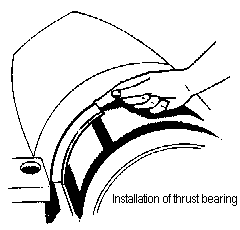 4) The thrust
bearing metal consists of upper and lower pieces. In assembly, take
care not to create one-sided contact and check side clearance well.
Be careful not to install it upside down. 4) The thrust
bearing metal consists of upper and lower pieces. In assembly, take
care not to create one-sided contact and check side clearance well.
Be careful not to install it upside down.
5) Before measuring
side clearance, move crankshaft toward front or rear using a crowbar.
Crankshaft
1) Although crankshaft is designed with ample
strength and rigidity, care should be taken as to the following
, which may result in crankshaft breakage:
1. When the engine
is operated for a long period at critical speed, with torsional
vibration
2. When operated with crankshaft deflection exceeding
the allowable limit.
3. When there is excessive clearance between
crankshaft and bearing, or uneven wear of crankshaft.
2) When
there is burning of crankshaft or bearing due to depletion of oil,
etc., carefully check for cranks using color penetrate check method
or the like.
3) When crankshaft must be reground because of
uneven wear or hair cracks consult manufacturer.
<Items to check and measure>
1. Scratches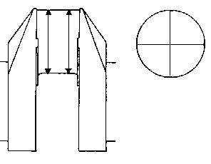 or dents on bearing surface,
condition of fit-up, uneven or abnormal wear or dents on bearing surface,
condition of fit-up, uneven or abnormal wear
2. Fillet portion
and lubricating oil hole in bearing (color penetrate testing method)
3. Soiling or clogging of lubricating oil hole
4. Loose balance
weight fixing bolt
5. Crankshaft deflection
6. Contours
of pin and journal
7. Surface hardness: if hardness degrades
below the specified value, consult with the manufacturer.
<Precautions for disassembly and re-assembly>
1. With sheeting, protect bearing pat from damage
during oil hole carefully and air blow dry.
2. Wash lubricating
oil hole carefully and air blow dry.
3. Clean bearing surface
thoroughly to keep it free from dirt.
Measurement of crankshaft
deflection
Timing
Gear, Camshaft and Related Parts
Timing gear
1) Overhaul timing gear
every two years; check gear tooth surfaces and perform color penetrant
check.
2) Improper backlash not only increases noise and vibration
but also creates pitting or burrs on tooth surfaces. Therefore,
during overhaul if anything abnormal is observed with regard to
the backlash, replace either the bearing or gear with a new one.
<Disassembly>
1. Disassembly connecting pipe.
2. Dismount auxiliary
equipment (Lubricating oil pump, cooling water pump. etc.)
3.
Remove idle gear shaft holder.
4. Remove gear case.
5. Remove
auxiliary equipment drive gears.
6. Extract idle gear.
7.
Crank gear is shrinkage-fit to crankshaft. Refrain from extracting
it unless it is replaced with a new one.
<Precautions>
1. Timing
gear tally marks are provided on the side of each gear. Check marks
carefully in assembling
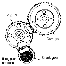 2. When extracting idle gear, bring the cutout portion
on auxiliary equipment drive gear mounting boss to the gear meshing
position and then extract it. 2. When extracting idle gear, bring the cutout portion
on auxiliary equipment drive gear mounting boss to the gear meshing
position and then extract it.
3. When shrinkage-fitting, heat
crank gear in oil bath to around 150¡180¢ªC and set it quickly
at specified position.
<Item
to check and measure>
1. Fit-up, wear
and pitting, if any, of tooth surface.
2. Contact and wear on
bearing and shaft
3. Loose bearing mounting bolt
4. Gear
backlash
5. Clearance between bearing and shaft
Camshaft
The camshaft is provided with a thrust bearing
which serves to prevent the shaft from moving in the axial direction.
If the clearance between bearing and shaft increases, breakage of
the governor driving bevel gear, or governor malfunction may occur.
Therefore, the clearance should be checked from time to time. If
camlift decreases due to an abraded cam, the camshaft should be
pulled to replace the cam with a new one.
<Disassembly>
1. Disassemble
gear case front cover
2. Disassemble governor drive gear.
3. Remove cam bearing (thrust bearing) at the front end.
4.
Extract cam bearing lubrication bolt (which is concurrently serving
as cam bearing locator)
5. After removing each tappet, move
camshaft toward governor side.
6. After cam bearing comes off
the engine frame ,disassemble cam bearing bolt.
7. Remove cam
bearing.
8. Extract camshaft toward governor side.
Cam
The intake and exhaust cams are shrinkage-fit to the camshaft directly;
the fuel cams are tightened on the taper sleeve.
<Extraction and installation>
1. With camshaft firmly second, knock cams out with a brass bar
or similar soft metal piece, or draw them out with an oil jack using
a suitable jig.
2. Detach fuel cam using fuel cam removing nut
and take it out with taper sleeve.
3. To make extraction and
installation easier, each cam, from shaft ends to center, has a
diameter 0.1mm larger than one before. Diameter is marked
on each cam.
4. Pay attention to the mark in reassembling and
install each cam in the correct position.
5. When installing the cams, heat them in
an oil bath to approximately 150¢ª¡180¢ªC and install them in their
prescribed positions. Take care not to heat over 180¢ªC ; otherwise,
the cam may be changed in structure and lose strength.
6. Misalignment
between cam and tappet roller should be kept to within 0.5mm. For
this purpose, it is advisable to put the position mark on the camshaft
before extracting the cam.
<Items
to check and measure>
1. Pitting or
wear on cam surface
2. Loosely fit cam
3. Clearance between
camshaft and bearing
4. Clearance between thrust bearing
Adjustment
of fuel cam
Fuel cam should be adjusted when Pmax is abnormal,
and only after the operator has clearly determined the true cause
of the disorder; it should never be handled without reason. The
data shown on the factory data sheet are for operation on diesel
fuel oil. When switching to heavy fuel oil, valve of Pmax and exhaust
gas temperature vary, bur no adjustment is needed for Pmax unless
it exceeds the prescribed limit.
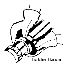 <Adjustment procedure> <Adjustment procedure>
1. The fuel oil cam removing nut is located at
the right side, and the fixing nut at the left in a standard engine.
Align the marked line on the removing nut with the base line on
the side of the cam and read the scale at the sleeve end. It is
recommended that the tappet roller be placed on the base circle
line of the cam.
In engines modified for reverse
rotation , be careful the positions of removing nut and tightening
nut are reverse of those in standard engines.
2. Loosen fixing nut (right- handed thread).
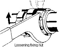 (Push wrench upward.) (Push wrench upward.)
3. Turn cam removing nut and detach taper sleeve of cam.
4.
Return removing nut, align to read position referring to cam shifting
hole and shift cam either to advance or delay position.
5. When
cam is shifted in the rotation direction, the timing become earlier.
The maximum combustion pressure Pmax change by 3¡5/cm2 per
notch on the cam scale.
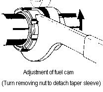 6. While holding cam, fix it in position by turning
tightening nut. 6. While holding cam, fix it in position by turning
tightening nut.
7. Put removing nut to collar end of taper sleeve
and clamp it. Never clamp it at the cam side.
<Precautions>
1. Deviation
between the Pmax¡¯s in the cylinders should be kept within 3kg/cm2
while observing the requirement of the ceiling; the total
pressure must not exceed design Pmax valve plus 3kg/cm2 in
any case.
Pmax is increased by advancing injection timing and
decreased by delaying it.
2. When tightening cam-fixing nut,
spray anti-seizure agent
Do
not spray anti-seizure agent on tapered portion.
As the taper sleeve breaks in quickly, check it periodically in
accordance with Maintenance intervals in instruction for each engine,
and tighten I further if necessary.
3. Misalignment between cam and tappet roller should be within 0.5mm.
Insufficient tightening of fuel
cam tightening nut may cause fuel cam slippage, resulting in ill-timed
fuel injection . To avoid this, take special care to tighten
nut securely to the specified torque.
Fuel
injection Pump
When fuel injection pump is replaced, align marked
line on plunger guide with basic line by means of push rod adjusting
shim inside tappet. However, fuel injection timing adjustment
via this shim, should strictly be avoided since the delivery via
may be pushed up with the plunger.
Fuel injection pump tappet
1) Since
extreme pressure will imposed on the tappet roller at the initial
pushing stage of the fuel cam, the utmost care should be taken that
the cam is completely parallel with the roller.
2) If the spring
inside the tappet is broken, the governor will malfunction or the
maximum combustion pressure will change.
Check the spring on such occasions.
3) If a scratched roller
is continuously used as it is, it may damage itself or the cam.
Accordingly, repair the scratch with an oil stone , etc. before
use.
4) Because the tappet roller bush is subject to great pressure,
it is liable to wear quickly; therefore timely inspection and wear
measurement are necessary.
5) The o-ring used for the fuel injection
pump mount should be replaced with a new one at each overhaul.
<Disassembly>
1. Take out fuel injection pump.
2. Extract fuel injection pump
mount.
3. Extract push rod
4. Extract tappet set screw on
mount.
5. Extract tappet.
6. Extract roller pin and take
out roller.
Intake and exhaust tappets
1) Intake
and exhaust tappets should be handled in the same as fuel injection
pump tappet.
2) If tappet roller outer diameter or roller shaft
and bush are abraded, valve end clearance increase, changing opening/closing
timing of intake and exhaust valves and adversely affecting combustion.
For this reason, periodic inspection and wear measurement are essential.
3) If sticky exhaust or intake valves is found, inspect it;
if left unattended, it may bend push rod or cause cracks in push
rod seat.
4) When push rod and protective pipe have been extracted,
cover hole so that no foreign matter can fall inside. Foreign
matter may damage push rod and seat.
<Disassembly>
1. Remove
push rod and protective pipe.
2. Disassemble tappet tightening
nut and extract tappet guide from engine frame.
3. Extract set
screw from tappet guide.
4. Extract tappet.
5. Extract roller
pin and take out roller.
Governor
Governor
1) Since the governor controls engine speed,
it should be maintained in the best working condition at all times.
2) The governor should nor be overhauled on site. Although the overhauling
procedures are described in the separate instruction, it is advisable
to have it overhauled by the manufacturer.
3) For further details
on handling, refer to separate manual for governor.
Governor driving gear
1) The governor
driving bevel gear is fitted at the leading end of the camshaft,
together with the pump driving gear, via a cushion spring which
frees the governor from torsional vibration.
2) To check the
condition of the cushion spring, turn gear in both directions while
checking fitting of gear tooth surfaces. Overhaul and inspect once
every two years.
<Disassembly>
1. Remove governor gear fixing nut.
2. Extract
pump driving gear and governor driving gear assemblies as assembled.
3. Remove pump driving gear set bolt.
4. Remove washers
for governor driving gear and pump driving gear
5. Remove
cushion spring and cushion spring seat.
<Precautions>
Do not over tighten governor driving gear tightening nut; otherwise,
cushion becomes ineffective.
Fuel control device
1) Refrain from
undue adjustment of fuel gear injection pump rack.
2) If link pin and other joint parts or level set screw come loose
misposition during operation, governor control is lost, resulting
in over-speed. To avoid this, check joint parts from time to time.
3) Governor link spring should not be disassembled. If disassembly
is absolutely necessary, measure and record spring fitting length
(L) so that it can be reassembled to precisely the same fitting
length. If the spring is fitted at a longer (weaker) length, the
force from the governor will no longer be transmitted.
Conversely,
if it is fitted at a shorter (strength) length, then the fuel cutoff
device cannot function.
4) Check for deflection in the governor
link system.
5) With control level set at stop position, check
that graduation on rack register ¡°0¡±
Inter cooler
1) The inter cooler is likely to be soiled at
the cooling water side and the air side. Inspect and clean it at
appropriate intervals, determined with reference to the Maintenance
intervals and according to the actual operating conditions of the
engine and loss in performance, if any.
2) Wet inside of cooling
pipe slightly with water and clean with a nylon brush.
3) Clean
outside of cooling pipe with compressed air. If soiled heavily
with oil, etc., dip cooling pipe, with water chamber detached, in
a neural detergent bath. After cleaning, rinse with clean water
and let dry.
4) Check condition of protective zinc once every
6 months. Adjust inspection interval depending on degree of wear.
5) The drain separator installed at the inter cooler air outlet
should also be cleaned at each overhaul.
Fuel Oil System
Fuel oil pump
1) Fuel oil pump specified
for use with Diesel fuel oil.
<Overhaul
and inspection>
1. Since the fuel oil
pump is small, there should never be any strain applied from external
piping, which may result in breakage of pump mount.
2. A check
valve is provided to allow fuel oil to flow down via the head when
the engine is at rest, permitting priming. Be careful of damage
to check valve or seat, which may result in depletion of fuel oil.
3. Average life of oil seal and ball bearing is two to three years.
<Precautions>
1. Take special care not lose the check valve, a tiny steel ball.
2. Do not use packing on mating surface of pump body and cover.
Apply proper sealant to mating surface.
3. Diesel fuel oil pump
of the same type is used for special specification fitted with nozzle
cooling system.
Lubricating
Oil System
Lubricating oil pump
1) The lubricating
oil pump is located under the crankshaft beside the auxiliary equipment
driving gear. Its backlash is designed to be slightly larger than
required so that it can drive the pump even after the main bearings
are worn. Backlash : 0.3¡0.6mm
2) Since the lubricating
oil pump is of the gear type , the clearance between casing and
gears is very closely related to volume of discharge and lift. Check
clearance at disassembly.
<Precautions>
1. Packing should not be used on the matching face between
section plate and pump cover, and between section plate and gear
box and pump body.
2. When installing driving gear, tapered
part should be tightened securely.
3. If suction pipe is not
adequately connected, pump may suck in air and pressure may not
rise. Therefore, see to it that pipe is connected positively.
4. Arrow mark indicating normal flow direction is provided on pump
cover. Assemble in correct direction so that oil release hole comes
to delivery side.
5. Be sure to overhaul safety valve provided
on pump cover and check for sticking. If any trace is fond, repair
place by lightly applying an oil stone.
6. Check bearing and
oil seal at time of overhaul and replace them as necessary.
Lubricating oil cooler
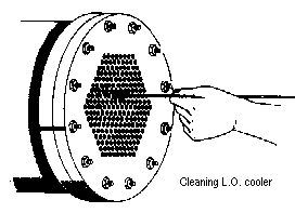 1) Accumulated sludge on surface of cooling tube reduces
cooling effect significantly. Wash periodically according to the
Maintenance intervals. 1) Accumulated sludge on surface of cooling tube reduces
cooling effect significantly. Wash periodically according to the
Maintenance intervals.
2) It is recommended that steam and neutral
detergent be used as Neos, etc., for effective cleaning. Carry out
post-washing treatment correctly.
3) Oil may leak at packing
due to expansion or shrinkage of internal cooling tube. Tighten
packing additionally from time to time to time or replace it with
new as required.
<Precautions>
1. The cooling tube should be handled with great care. Be sure not
to apply heat over 150¢ªC to joint between holder plate and cooling
tube.
2. A hydrostatic test should be conducted after the oil
cooler is assembled.
Lubricating oil pressure regulating valve.
1) If oil pressure fails to rise even after the adjusting screw
is driven in, the valve may be struck. Check valve after checking
for other possible causes for low oil pressure; oil shortage, air
entry, defective lubricating system , etc.
2) If valve is struck,
pressure change significantly, depending on oil viscosity and engine
speed. If the pressure change exceeds 1.5kg/cm2, check the valve.
It should be remembered, however, that oil pressure may increase
over the specified valve when the engine speed is increase rapidly
during cold weather, but as the oil temperature raises, oil pressure
will drop to normal.
<Precautions>
1. When overhauling, carefully inspect for sludge accumulation
in oil passage and regulating valve. If necessary, remove and clean.
2. If any scratches are noted on pressure regulating valve, dress
with oil stone, and check that valve moves lightly.
Rocker Arm Lubricating System Related Parts
<Precautions>
1. Pump
rotor and drive shaft are tiny parts. Handle them with beat care
and do not remove out forcibly.
2. Oil seal, o-ring and packing
should be replaces with new ones.
3. Check and clean safety
valve incorporated in pump cover when overhauling.
4. Overhaul
and check pump once every two years.
5. Drive shaft and rotor
(both inner and outer parts) should me replaces as a set.
Rocker arm lubricating oil filter
1.
Since rocker arm lubricating system lubricates sections subject
to heavy contamination, drainage at least once a week and overhaul
and cleaning once a month are necessary.
2. Pressure regulating
valves and oil tank used in the system should also be overhauled
and cleaned from time to time.
Rocker arm lubricating
oil pressure regulating valve.
<Precautions>
1. When disassembling,
thoroughly remove sludge accumulated in oil passage and pressure
regulating valve.
2. When reassembling, check for deformed packings
and replace with new if worm heavily.
Cooling
Water System
Cooling water pump
1. Check thoroughly
for wear of impeller and mouth ring as wear in these parts tends
to lower pump head. (Allowable wear limit)
Clearance
between mouth ring and impeller; 0.75mm
2. Mechanical seal is
an important part that seals pump chamber from atmosphere. If it
is fit inadequately, water leakage may result from air chamber at
back of section wall via drain pipe. Average life of mechanical
seal: 4,000¡6,000hrs.
3. Cooling water pump run at 2,000 rpm
on average is directly coupled with engine and subject to engine
vibration. Therefore, ball bearing used therein is most likely to
wear. Overhaul the pump and replace ball bearing with new one at
regular intervals. Average life of ball bearings 7,000 to 10,000hrs.
It is desirable to replace the ball bearing earlier, since continued
use of a worn bearing may result in driving gear damage at crankshaft
side, involving unnecessarily higher repair cost.
4. Since the
pump section is subject to servere vibration, check carefully for
pitting or scratching on gear face when overhauling. Such surface,
if any, should be dressed with a set of files or the gear as a whole
with a new one if it has worn beyond the allowable limit.
5.
As allowance for ambient temperature fluctuation or strain causes
by faulty piping, driving gear is made to tolerate a backlash of
0.3 to 0.6 mm
6. Other items to check
.Traces of cavitation
or corrosion on impeller
.Drive shaft wear at oil seal sliding
portion
.Deterioration or cracks on oil seal rubber
<Disassembly>
1. Remove connecting pipe.
2. Remove pump cover.
3. Loosen
impeller tightening nut.
In standard engine specification, the
nut is left-hand threaded (turned clockwise to loosen when viewed
from flywheel.)
4. Remove impeller.
Impeller is fixed on
taper-fit method. To loosen it, strike the vane end two to three
times with a wooden hammer. The use of a jig is also recommended
for extracting impeller.
5. Remove mechanical seal .
6.
Dismount pump body.
7. Remove seal holder.
8. Remove driving
gear fixing nut.
9. Extract driving gear.
10. Remove bearing
holders.
11.Extract shaft along with ball bearing
12. Extract
bearing from shaft. (Shape of bearing differs slightly, according
to the type of engine.)
<Precautions>
Do not get oil on carbon part of mechanical seal.
Incorporate oil seal in the right direction as shown in the exploded
view below. |
![]()



 1. Operate the nozzle tester hand lever at as stroke
of 4¡6 time per second and check the spray mist to see that it
is uniform without abnormality due to the blocked injection hole.
Shown below are different condition of fuel spraying through
injection nozzle.


 1. Bring intake
and exhaust valves for cylinder to be measured to fully closed positions.
(At this position, graduation marked on flywheel points to TOP position
, with the marked line on the fuel injection pump at the up position.)
 6. Even if bearing abrasion
is still within the allowable limit, if it is used for a long time,
it loses tension. Which may cause cracks. Therefore, it is better
to replace it with a new one after 4 years or so of operation.
 Roughness or
scratches on surface, if any, should be repaired by machining or
otherwise.
 b) Attach large-end cap without bearing
metal; using a torque wrench, tighten bolts to torque A (follow
as specified each engine)
 <Measurement>
 Then
replace cap and tighten to prescribed torque. Remove cap and measure
with a micrometer the thickness of the lead wire thus pressed.
 4) The thrust
bearing metal consists of upper and lower pieces. In assembly, take
care not to create one-sided contact and check side clearance well.
Be careful not to install it upside down.
 or dents on bearing surface,
condition of fit-up, uneven or abnormal wear
 2. When extracting idle gear, bring the cutout portion
on auxiliary equipment drive gear mounting boss to the gear meshing
position and then extract it.
 <Adjustment procedure>
 (Push wrench upward.)
 6. While holding cam, fix it in position by turning
tightening nut.
 1) Accumulated sludge on surface of cooling tube reduces
cooling effect significantly. Wash periodically according to the
Maintenance intervals.